
Flight Parameters
 This is the total aircraft weight in ounces or grams. Stored in Planes database. Don't forget to adjust the weight if you change motors. This weight should
be appropriate for the number and type of cells you have entered, since the
program adjusts the weight with cell changes. ElectriCalc is not ambitious enough
to keep up with the weight of hundreds of motor/gearbox combinations (or the
weight of different props for that matter!).
This is the total aircraft weight in ounces or grams. Stored in Planes database. Don't forget to adjust the weight if you change motors. This weight should
be appropriate for the number and type of cells you have entered, since the
program adjusts the weight with cell changes. ElectriCalc is not ambitious enough
to keep up with the weight of hundreds of motor/gearbox combinations (or the
weight of different props for that matter!).
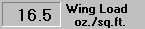 This is the wing loading, or ratio of plane weight to total wing area
expressed in ounces per square foot or grams per square decimeter. This value is
calculated and not stored in any database. If you enter a value for wing loading, the
Plane Wt. and Wing Area will "light up". Double-clicking on either of these
will recalculate that value to correspond to the specified loading. This is
useful for things like determining a target weight for a model when you know the
wing area and the desired wing loading Tolerable wing loading goes up as the size
of the plane increases. 18 oz. per sq. ft. is good for "Speed 400" size planes.
24 oz. per sq. ft. is good for "40-size" planes. 30+ oz. per sq. ft. can be
tolerated in the very large models. Biplanes require lower loading because the
two wings in close proximity are not as efficient.
This is the wing loading, or ratio of plane weight to total wing area
expressed in ounces per square foot or grams per square decimeter. This value is
calculated and not stored in any database. If you enter a value for wing loading, the
Plane Wt. and Wing Area will "light up". Double-clicking on either of these
will recalculate that value to correspond to the specified loading. This is
useful for things like determining a target weight for a model when you know the
wing area and the desired wing loading Tolerable wing loading goes up as the size
of the plane increases. 18 oz. per sq. ft. is good for "Speed 400" size planes.
24 oz. per sq. ft. is good for "40-size" planes. 30+ oz. per sq. ft. can be
tolerated in the very large models. Biplanes require lower loading because the
two wings in close proximity are not as efficient.
 This is the total wing area in square inches or square decimeters. Stored in Planes database. Wing area is normally considered to include the area over/under the
fuselage. The area of a wing with non-parallel leading & trailing edges can be figured
by taking the width at the center plus the width at the tip and multiplying by
the length (perpendicular to fuselage) from the center to the tip.
This is the total wing area in square inches or square decimeters. Stored in Planes database. Wing area is normally considered to include the area over/under the
fuselage. The area of a wing with non-parallel leading & trailing edges can be figured
by taking the width at the center plus the width at the tip and multiplying by
the length (perpendicular to fuselage) from the center to the tip.
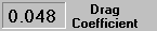 This is an aerodynamic constant used in calculating the thrust required to
move the plane through the air at a given speed. Stored in Planes database This number can be entered here or a reasonably good estimate can be quickly
made by selecting C drag from the menubar.. Wing struts and wires add a lot of drag. A good
aerodynamics text is "Model Airplane Design and Performance for the Modeler" by Howard
Chevalier. Reduction of drag in electric models is quite important. Biplanes in
particular give disappointing flight times. Thick airfoils, fat fuselages,
struts and wires should be avoided or minimized wherever possible. Remember that
wing loading also contributes to drag.
This is an aerodynamic constant used in calculating the thrust required to
move the plane through the air at a given speed. Stored in Planes database This number can be entered here or a reasonably good estimate can be quickly
made by selecting C drag from the menubar.. Wing struts and wires add a lot of drag. A good
aerodynamics text is "Model Airplane Design and Performance for the Modeler" by Howard
Chevalier. Reduction of drag in electric models is quite important. Biplanes in
particular give disappointing flight times. Thick airfoils, fat fuselages,
struts and wires should be avoided or minimized wherever possible. Remember that
wing loading also contributes to drag.
 This is an alphanumeric representation of the motor configuration. Stored in Planes database. Information cannot be entered directly here, but can be selected by clicking
the raised panel or the Multi menubar selection. Two motors in parallel have the same Kv , half the Rm , and twice the Io . Two in series have half the Kv, twice the Rm, and the same Io. Etc, etc.
This is an alphanumeric representation of the motor configuration. Stored in Planes database. Information cannot be entered directly here, but can be selected by clicking
the raised panel or the Multi menubar selection. Two motors in parallel have the same Kv , half the Rm , and twice the Io . Two in series have half the Kv, twice the Rm, and the same Io. Etc, etc.
 This is a description of the selected plane. Stored in Planes database.
 This is the Planes database control. If you click the big button, you jump to the Planes database. The
smaller buttons step you back and forth through the database. Use CTRL_S as a shortcut to access the database. This selects the plane that is displayed. This
includes the cell count, wiring resistance, prop diameter & pitch, weight, wing area,
Cdrag, and motor configuration. It also selects a cell, motor/gearbox, and
prop from their respective databases.
This is the Planes database control. If you click the big button, you jump to the Planes database. The
smaller buttons step you back and forth through the database. Use CTRL_S as a shortcut to access the database. This selects the plane that is displayed. This
includes the cell count, wiring resistance, prop diameter & pitch, weight, wing area,
Cdrag, and motor configuration. It also selects a cell, motor/gearbox, and
prop from their respective databases.
 This is the rate of climb at the maximum climb angle possible at the current throttle and speed slider settings. Climb rate drops off dramatically with speed because the
drag increases as roughly the square of the speed, and the available thrust drops
with increasing speed. The climb rate has a peak between stall and max speeds
that is related to the lift, drag, and thrust relationships.
This is the rate of climb at the maximum climb angle possible at the current throttle and speed slider settings. Climb rate drops off dramatically with speed because the
drag increases as roughly the square of the speed, and the available thrust drops
with increasing speed. The climb rate has a peak between stall and max speeds
that is related to the lift, drag, and thrust relationships.
 This is the maximum sustainable climb angle at the current throttle and speed
slider settings. It corresponds to the climb rate above. Physically, this
number is derived from the amount of thrust remaining to lift the plane after
subtracting that necessary to pull the plane through the air at the set speed. Climb
angle (sustained) drops off dramatically with speed because the drag increases
as roughly the square of the speed, and the available thrust also drops with
increasing speed
This is the maximum sustainable climb angle at the current throttle and speed
slider settings. It corresponds to the climb rate above. Physically, this
number is derived from the amount of thrust remaining to lift the plane after
subtracting that necessary to pull the plane through the air at the set speed. Climb
angle (sustained) drops off dramatically with speed because the drag increases
as roughly the square of the speed, and the available thrust also drops with
increasing speed
 This is the maximum rate of climb obtainable at the current throttle setting,
independent of the speed slider. It is obtained at the angle indicated. The
steepest climb angle does not yield the fastest climb.
This is the maximum rate of climb obtainable at the current throttle setting,
independent of the speed slider. It is obtained at the angle indicated. The
steepest climb angle does not yield the fastest climb.
 This is the theoretical total height at the max climb rate for the indicated
minutes. Although this number is calculated by multiplying the calculated max
climb rate times the calculated minutes, it's really just a relative measure. It
does not integrate this number over the discharge profile of the battery pack.
This is the theoretical total height at the max climb rate for the indicated
minutes. Although this number is calculated by multiplying the calculated max
climb rate times the calculated minutes, it's really just a relative measure. It
does not integrate this number over the discharge profile of the battery pack.
 This is the theoretical minimum flying speed using a rule of thumb based on
the wing loading. It is only an approximation but normally close enough. This
number is the standard rule of thumb of 3.7 times the square root of the wing
loading in oz. per sq. ft or grams per sq. dm.
This is the theoretical minimum flying speed using a rule of thumb based on
the wing loading. It is only an approximation but normally close enough. This
number is the standard rule of thumb of 3.7 times the square root of the wing
loading in oz. per sq. ft or grams per sq. dm.
 This is the calculated maximum plane speed in level flight based on the thrust
of the prop(s) and the drag of the plane. This is the speed where the thrust
and drag curves cross. Climb rate is zero because there is no thrust available
to lift the plane.
This is the calculated maximum plane speed in level flight based on the thrust
of the prop(s) and the drag of the plane. This is the speed where the thrust
and drag curves cross. Climb rate is zero because there is no thrust available
to lift the plane.
 This is a magic number computed by ElectriCalc to give you a measure of flying
time assuming mild maneuvers and good throttle management. This number is
based on sustaining an average climb rate and speed related to the rate-of-climb
vs. speed curve. This calculated speed is then obtained by backing off the
throttle and then calculating the run time. It's just a guideline, not something to
lose sleep over.
This is a magic number computed by ElectriCalc to give you a measure of flying
time assuming mild maneuvers and good throttle management. This number is
based on sustaining an average climb rate and speed related to the rate-of-climb
vs. speed curve. This calculated speed is then obtained by backing off the
throttle and then calculating the run time. It's just a guideline, not something to
lose sleep over.
 This �speedometer� control sets the speed at which you want the performance calculations made.
More speed . . . less climb, more drag . . . less thrust, etc. Clicking the
arrows steps 1% and clicking in the white area steps 5%. Try stepping the speed
from stall to max and watching the rate of climb first increase and then decrease.
This �speedometer� control sets the speed at which you want the performance calculations made.
More speed . . . less climb, more drag . . . less thrust, etc. Clicking the
arrows steps 1% and clicking in the white area steps 5%. Try stepping the speed
from stall to max and watching the rate of climb first increase and then decrease.