
Power Parameters
 This is simply the number of cells in your flight battery pack. Stored in Planes database. The most popular values are 7 and 10 cells. It is common to hook packs in
series to make larger sizes. If you need to model two packs in parallel, create a
new cell type with half the Cell mohm and twice the MAH and name it something
like "2xRC2000".
This is simply the number of cells in your flight battery pack. Stored in Planes database. The most popular values are 7 and 10 cells. It is common to hook packs in
series to make larger sizes. If you need to model two packs in parallel, create a
new cell type with half the Cell mohm and twice the MAH and name it something
like "2xRC2000".
 This is the nominal internal cell voltage. Stored in file ECALC.INI . This is not the voltage you would measure under load, since this would also
include the drop due to the internal resistance. A NiCad normally starts at
1.30-1.35 volts, levels off at around 1.25, and at 1.20 is about empty! The
simple model of a NiCad cell is an ideal voltage source and a series resistance.
During the 'plateau' of the discharge curve the voltage drops a few hundredths of
a volt. We have measured 1.25 as a typical value but some feel that a slightly
lower number is more realistic.
This is the nominal internal cell voltage. Stored in file ECALC.INI . This is not the voltage you would measure under load, since this would also
include the drop due to the internal resistance. A NiCad normally starts at
1.30-1.35 volts, levels off at around 1.25, and at 1.20 is about empty! The
simple model of a NiCad cell is an ideal voltage source and a series resistance.
During the 'plateau' of the discharge curve the voltage drops a few hundredths of
a volt. We have measured 1.25 as a typical value but some feel that a slightly
lower number is more realistic.
 This is the equivalent cell resistance in milliohms. Stored in Cells database. The lowest resistance is obtained with end-end soldered cells. Cell
resistance should include the resistance of the cell interconnections. The original
data assumes minimal (end-end soldered) resistance. Bars or heavy braid will be
somewhat more (+0.5 milliohm) and welded tabs could be substantially more (>1
milliohm). You can measure this yourself with a good DVM, ammeter, and load.
Basically you need to measure under load and no-load voltage quickly so that
chemical processes do not interfere. Use at least a 10-amp load. Cell resistance is
voltage difference divided by load current divided by number of cells. See our web site for information on end-end packs.
This is the equivalent cell resistance in milliohms. Stored in Cells database. The lowest resistance is obtained with end-end soldered cells. Cell
resistance should include the resistance of the cell interconnections. The original
data assumes minimal (end-end soldered) resistance. Bars or heavy braid will be
somewhat more (+0.5 milliohm) and welded tabs could be substantially more (>1
milliohm). You can measure this yourself with a good DVM, ammeter, and load.
Basically you need to measure under load and no-load voltage quickly so that
chemical processes do not interfere. Use at least a 10-amp load. Cell resistance is
voltage difference divided by load current divided by number of cells. See our web site for information on end-end packs.
 This is the equivalent resistance of the ESC (Electronic Speed Control) plus all the wiring and the connectors, fuse(s), and switch(es). Stored in Planes database . The resistance of ESCs is a function of design and number and type of FETs.
Also, brushless controllers have inherently higher resistance because they
must switch both sides of the winding and this requires p-channel FETs with higher
resistance. High performance brushless controllers have a bunch of FETs.
This is the equivalent resistance of the ESC (Electronic Speed Control) plus all the wiring and the connectors, fuse(s), and switch(es). Stored in Planes database . The resistance of ESCs is a function of design and number and type of FETs.
Also, brushless controllers have inherently higher resistance because they
must switch both sides of the winding and this requires p-channel FETs with higher
resistance. High performance brushless controllers have a bunch of FETs.
 This is the typical milliampere-hour capacity of a cell. Stored in Cells database . This basically means that the cell can supply that many milliamps for one
hour before the voltage drops substantially. This is generally higher than the
manufacturer's rating, but will vary as a function of the charge method,
discharge rate, and temperature. This number is used to estimate the motor run time at
the calculated battery current. MAH is normally measured assuming a cutoff
voltage of one volt or less. With high cell-count packs you can't afford to let
the pack get down this low per cell without risking damage to the lower-capacity
cells. You can expect the capacity of a higher cell-count pack to appear less
due to the higher probability of a spread in cell capacities.
This is the typical milliampere-hour capacity of a cell. Stored in Cells database . This basically means that the cell can supply that many milliamps for one
hour before the voltage drops substantially. This is generally higher than the
manufacturer's rating, but will vary as a function of the charge method,
discharge rate, and temperature. This number is used to estimate the motor run time at
the calculated battery current. MAH is normally measured assuming a cutoff
voltage of one volt or less. With high cell-count packs you can't afford to let
the pack get down this low per cell without risking damage to the lower-capacity
cells. You can expect the capacity of a higher cell-count pack to appear less
due to the higher probability of a spread in cell capacities.
 This is a description of the selected cell. Stored in the Cells database . These cells are mainly Sanyo. The most popular are the N-1700SCRC and
RC2000 for sport flying, and the KR-600AE and N-500AR for the smaller "Speed 400"
models. This brand has a proven track record. Cells with an 'R' in the suffix are
especially suited for the high charge and discharge rates needed for electric
flight. Other cells have a higher energy to weight ratio but at the expense of
lower current handling and/or charge rate.
This is a description of the selected cell. Stored in the Cells database . These cells are mainly Sanyo. The most popular are the N-1700SCRC and
RC2000 for sport flying, and the KR-600AE and N-500AR for the smaller "Speed 400"
models. This brand has a proven track record. Cells with an 'R' in the suffix are
especially suited for the high charge and discharge rates needed for electric
flight. Other cells have a higher energy to weight ratio but at the expense of
lower current handling and/or charge rate.
 This is the Cells database control. If you click the big button, you jump to
the Cells database. The smaller buttons step you back and forth through the database. Use CTRL_C
as a shortcut to access the database. This selects the cell information on the screen which
includes cell resistance, cell capacity in MAH, and a description of the cell.
This is the Cells database control. If you click the big button, you jump to
the Cells database. The smaller buttons step you back and forth through the database. Use CTRL_C
as a shortcut to access the database. This selects the cell information on the screen which
includes cell resistance, cell capacity in MAH, and a description of the cell.
 This is the current supplied by the battery. It is equal to the motor current
at full throttle and less than the motor current at partial throttle. For
motors wired in parallel, the battery current is the total to all motors. At part
throttle, battery amps will be less than motor amps. This seems wrong, but what
is happening is sort of a transformer effect. The watts out of the battery are
roughly the same as the watts into the motor. However, the ESC essentially
lowers the average motor voltage. If you have the same wattage, you must have more
current. How can this be? When the ESC switches off the motor. The current in
the motor continues to flow via a special diode or equivalent in the ESC.
This is the current supplied by the battery. It is equal to the motor current
at full throttle and less than the motor current at partial throttle. For
motors wired in parallel, the battery current is the total to all motors. At part
throttle, battery amps will be less than motor amps. This seems wrong, but what
is happening is sort of a transformer effect. The watts out of the battery are
roughly the same as the watts into the motor. However, the ESC essentially
lowers the average motor voltage. If you have the same wattage, you must have more
current. How can this be? When the ESC switches off the motor. The current in
the motor continues to flow via a special diode or equivalent in the ESC.
 This is the estimated battery duration at the indicated current. This number
is often much lower than the flight time you would like. The key to success is
intelligent use of the throttle.
This is the estimated battery duration at the indicated current. This number
is often much lower than the flight time you would like. The key to success is
intelligent use of the throttle.
 This is the percentage of total energy that is delivered to the propeller.
This does not include any propeller losses, but includes losses in the cells,
wiring, ESC, and the motor itself. Generally, efficiencies below 45% for ferrite
motors and 50% for others indicates an overloaded system. Use the System Efficiency graph to figure out where the problem is.
This is the percentage of total energy that is delivered to the propeller.
This does not include any propeller losses, but includes losses in the cells,
wiring, ESC, and the motor itself. Generally, efficiencies below 45% for ferrite
motors and 50% for others indicates an overloaded system. Use the System Efficiency graph to figure out where the problem is.
 This is the power supplied by the �ideal� battery, not including losses due to internal cell resistance. This is the
denominator in determining system efficiency. In the ideal cell model, this is
the cell open-circuit voltage times the current times the number of cells.
This is the power supplied by the �ideal� battery, not including losses due to internal cell resistance. This is the
denominator in determining system efficiency. In the ideal cell model, this is
the cell open-circuit voltage times the current times the number of cells.
 This is the power loss in the battery, wiring, and ESC. Most of the loss will
be in the pack itself, so the lower the cell resistance the better. It's not a
bad idea to check your wiring with a DVM with the motor running to look for
excessive voltage drops. At 20A, you should generally see less than 0.02V across
connectors & switches.
This is the power loss in the battery, wiring, and ESC. Most of the loss will
be in the pack itself, so the lower the cell resistance the better. It's not a
bad idea to check your wiring with a DVM with the motor running to look for
excessive voltage drops. At 20A, you should generally see less than 0.02V across
connectors & switches.
 This is an estimate of the pack weight based on the weight per cell from the Cells database plus a small amount for solder and shrink wrap. End-end soldering yields the
lightest packs. Braid works well but a lot of solder can wick into the braid.
You can save a little weight by removing the wrapper(s) but you must be REALLY
careful how you handle the cells and how you insulate the pack.
This is an estimate of the pack weight based on the weight per cell from the Cells database plus a small amount for solder and shrink wrap. End-end soldering yields the
lightest packs. Braid works well but a lot of solder can wick into the braid.
You can save a little weight by removing the wrapper(s) but you must be REALLY
careful how you handle the cells and how you insulate the pack.
 This is the current at which the % system efficiency will be maximized. This
always occurs at a lower current than the maximum motor efficiency current. For
sport flying you don't want your full-throttle current to be this low. It's
better to prop for something higher than max. sys. eff. current, and use your
throttle.
This is the current at which the % system efficiency will be maximized. This
always occurs at a lower current than the maximum motor efficiency current. For
sport flying you don't want your full-throttle current to be this low. It's
better to prop for something higher than max. sys. eff. current, and use your
throttle.
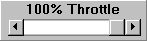 This is the duty cycle of the (high rate) ESC. This is controlled by a �slider� control. This reduces the average voltage seen by the motor(s). Clicking the
arrows steps 1% and clicking in the white area steps 5%. Set your speed for
twice stall speed and then back off the throttle until you get a 5-degree
climbout. This is a good upper bound on your expected flight time.
This is the duty cycle of the (high rate) ESC. This is controlled by a �slider� control. This reduces the average voltage seen by the motor(s). Clicking the
arrows steps 1% and clicking in the white area steps 5%. Set your speed for
twice stall speed and then back off the throttle until you get a 5-degree
climbout. This is a good upper bound on your expected flight time.