
Flight Pack Construction
(updated 2/13/02)
|
|
|
Flight Pack Construction
|
I have read about end-to-end battery techniques and have tried it with varying degrees of success. I have settled into a combination of techniques that I am finally comfortable with. I hope that some of the ideas and pictures prove helpful to someone trying this technique for the first time. Feel free to mix and match your own ideas. I start the process with cells from B&T R/C Products or Magellan Technologies. I have been pleased with service, and price is reasonable. If available, I use matched cells. I feel that 50 cents more per cell is a fair price to know for sure that your pack is not being limited by a lower capacity cell.
Below are the parts needed to assemble a pack.

This example shows the parts for a 10-cell CP-1700SCR pack.
These cells are the greatest thing since sliced bread, but that's another story.
Also shown (CCW from bottom left) are wire, Anderson Power Pole connector shells and contacts, battery bar,
1-1/2" and 2-1/2" heat shrink tubing (HST), nylon insulators (donuts), and end caps.
These materials are available from New Creations and/or B&T.
I generally use 16-gauge wire for Speed 400 packs and 13-gauge wires for higher current apps.
I use APP connectors (Sermos are APP connectors made to Sermos material specs) because they are economical, versatile,
and reliable.
A good source of especially lightweight tubing is Air dynamics (formerly NY Blimp).
The donuts keep solder splashes from causing problems and cells from shorting together.
I don't think the donuts are available for the smaller diameter cells.
You can use masking tape. I stick a piece over the button end then use a sharp #11 blade to cut out the center along the edge of the button.
The end caps are not absolutely necessary, but make the job look more professional.
Note that I have drilled a small hole in the blank endcap to allow probing with a meter to help check for a weak cell.
Next are the soldering tools I use to assemble a pack.
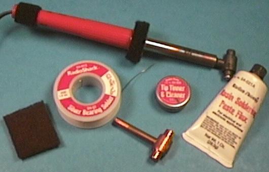
I use a Weller SP40 40-watt iron with a special "hammerhead" tip. A new tip is also shown in the picture.
The purpose of this tip is to provide a large thermal mass and two parallel soldering surfaces to heat two cells simultaneously.
The best tip IMHO is available from Charlie White.
The solder is Radio Shack 64-013 silver-bearing solder (62% tin, 36% lead, 2% silver).
I use Radio Shack 64-021A rosin paste flux .
Radio Shack 64-020 tip tinner is helpful for initially tinning the hammerhead.
Finally, a Scotchbrite pad is used for cleaning the contacts before tinning.
Other tools include a paint stripper (or other heat gun that can shrink tubing safely), pliers, diagonal cutters,
an Xacto knife, scissors, and wire strippers.
Now let's get to work!
First remove the insulation from each cell.
I do this for 3 reasons.
The insulation gets in the way of the iron when you are trying to pull it out quickly,
it's easier to inspect the solder joints & remove excess solder, and finally, it looks cool!
Just remember that these little cylinders are portable welding machines!
It's best to work with fully discharged cells.
You should mark the measured capacity with a permanent marker if you cannot keep track of cell capacities.
I do not, but mark each pack with an alpha-numeric ID when I am done.

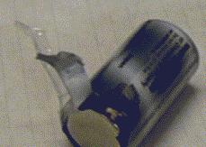
I start by cutting into the wrapper(s) with an X-acto knife at the NEGATIVE end of the cell.
I then pull (tear) the wrapper off with needle-nosed pliers.
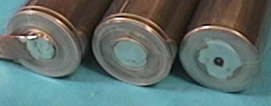
Next clean the ends of the cells with Scotchbrite or fine sandpaper until they are shiny.
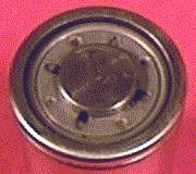
Gather all the cells with the positive button up.
Place a dollop of flux on one button, then rub another button against this.
Do this with other cells until you've placed a fine coat of flux on several buttons.
Repeat this until all buttons are fluxed.
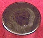
Use your hammerhead tip to tin all the buttons.
Place a SMALL amount of solder on the tip (1/8"-1/4") and swirl the tip over the button until the button is completely
tinned, or 3 seconds, whichever comes first.
If 3 seconds was not enough, you didn't get it clean enough or your technique is lacking.
You should have no blobs.
After you've done the whole batch, clean off the flux.
I use denatured alcohol and tissues for this.
Repeat this process for the other end of each cell. Try for a tinned spot somewhat bigger than the button.
Now attach the donuts to the positive ends with pieces of 3/4" masking tape.
The tape will be carefully removed after the cells are attached.
The newer cells do not provide as much clearance between cells,
but still enough room for a donut with wrapper removed.
One cell per stick does not need a donut at this time.
 Now you're ready to solder them together.
When I first started, I used the Ralph Weaver bench test for solder joint quality.
You smack the soldered cells on your bench and if they come apart the joint is bad!
I had an 80% success rate (1 out of 5 joints broke) using a 40-watt iron with a brand-X "hammerhead" tip.
I then got an 80-watt iron and didn't do much better.
I concluded that my problem was not getting the iron out and the cells together fast enough.
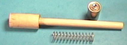
Consequently, I made a fixture.
This removed most of my incompetence from the process.
It consists of a 6" 2x4, an 18" piece of 1" corner mold, a 1" x 2" wood dowel, a 1" x 3" dowel,
a 1/2" x 6" dowel, and a 5/8" x 2-1/2" soft spring.
Notch the 2x4 to hold the corner mold.
Drill the 3" dowel through with a 1/2" drill to allow the 1/2" dowel to move smoothly inside.
Drill the 2" dowel about half-way through and glue the 6"dowel to form a plunger.
Glue the corner mold to the 2x4 and the 3" dowel to the corner mold.
Hobby Lobby sells a magnetic jig but I haven't tried it.
Now you're ready to solder them together.
When I first started, I used the Ralph Weaver bench test for solder joint quality.
You smack the soldered cells on your bench and if they come apart the joint is bad!
I had an 80% success rate (1 out of 5 joints broke) using a 40-watt iron with a brand-X "hammerhead" tip.
I then got an 80-watt iron and didn't do much better.
I concluded that my problem was not getting the iron out and the cells together fast enough.
Consequently, I made a fixture.
This removed most of my incompetence from the process.
It consists of a 6" 2x4, an 18" piece of 1" corner mold, a 1" x 2" wood dowel, a 1" x 3" dowel,
a 1/2" x 6" dowel, and a 5/8" x 2-1/2" soft spring.
Notch the 2x4 to hold the corner mold.
Drill the 3" dowel through with a 1/2" drill to allow the 1/2" dowel to move smoothly inside.
Drill the 2" dowel about half-way through and glue the 6"dowel to form a plunger.
Glue the corner mold to the 2x4 and the 3" dowel to the corner mold.
Hobby Lobby sells a magnetic jig but I haven't tried it.
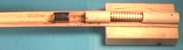
 I fasten the jig to my bench with a clamp.
Note that I am left-handed, so most people will be more comfortable with the plunger to the left.
Place a cell against the plunger and compress the spring for a modest amount of pressure.
About 3/8" works for me. You don't want to send a cell into the next room.
Make a mark on the corner mold at the end of the cell (not the plunger).
The plunger should always be against the flat end of the cell.
Using masking tape, tape the first cell to the jig so that the flat end is at the mark and the button end is pointing away from the plunger.
This cell does not need a donut.
Hint: center tape over cell and bring it firmly down to both sides of the jig, but do not allow the ends to touch.
You will be removing this tape a lot.
Take the second cell and place it between the first cell and the plunger.
If the mark is right, it should be held with modest pressure.
I fasten the jig to my bench with a clamp.
Note that I am left-handed, so most people will be more comfortable with the plunger to the left.
Place a cell against the plunger and compress the spring for a modest amount of pressure.
About 3/8" works for me. You don't want to send a cell into the next room.
Make a mark on the corner mold at the end of the cell (not the plunger).
The plunger should always be against the flat end of the cell.
Using masking tape, tape the first cell to the jig so that the flat end is at the mark and the button end is pointing away from the plunger.
This cell does not need a donut.
Hint: center tape over cell and bring it firmly down to both sides of the jig, but do not allow the ends to touch.
You will be removing this tape a lot.
Take the second cell and place it between the first cell and the plunger.
If the mark is right, it should be held with modest pressure.
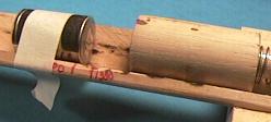
 Time to solder.
Let the iron get plenty hot. If the tip is new, tin it thoroughly with rosin-core solder.
Use a wet paper towel or fine sponge to wipe off the iron.
This should be done frequently to keep both tips clean and shiny.
Wet the tips like you did to tin the cells. Not a lot, but you need some for quick heat transfer.
No flux this time.
Pull the loose cell back with the plunger so there is plenty of room for the hammerhead.
Try to align the head so that, when you slowly move the cell back,
the head will be centered on the cells and contact both at about the same time.
Raise and lower the handle of the iron to spread the heat.
Three seconds MAX. That's "one monkey two monkey three monkey".
You should have one hand on the loose cell.
Ease the pressure on the head and quickly remove the iron and guide the cells together.
This should only take a fraction of a second.
Let the cells cool for at least 15 seconds.
Carefully remove the tape from the jig without disturbing the cells.
Slide the cells until the 2nd cell is lined up with the mark.
Retape the first cell and tape the 2nd cell.
Repeat the process until you have a complete stick.
Time to solder.
Let the iron get plenty hot. If the tip is new, tin it thoroughly with rosin-core solder.
Use a wet paper towel or fine sponge to wipe off the iron.
This should be done frequently to keep both tips clean and shiny.
Wet the tips like you did to tin the cells. Not a lot, but you need some for quick heat transfer.
No flux this time.
Pull the loose cell back with the plunger so there is plenty of room for the hammerhead.
Try to align the head so that, when you slowly move the cell back,
the head will be centered on the cells and contact both at about the same time.
Raise and lower the handle of the iron to spread the heat.
Three seconds MAX. That's "one monkey two monkey three monkey".
You should have one hand on the loose cell.
Ease the pressure on the head and quickly remove the iron and guide the cells together.
This should only take a fraction of a second.
Let the cells cool for at least 15 seconds.
Carefully remove the tape from the jig without disturbing the cells.
Slide the cells until the 2nd cell is lined up with the mark.
Retape the first cell and tape the 2nd cell.
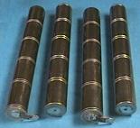
Repeat the process until you have a complete stick.
 Carefully set this aside and repeat the process for the remaining stick(s).
Do not let these lay side-by-side!
When they've cooled, carefully remove the masking tape.
Use your thumb and index finger and hold as close to the donut as possible.
With the newer cells, it's not easy to remove tape and solder splats.
The older cells allowed room for an X-acto blade.
Perhaps real thin piano wire will work.
I've been trying to think of a way to quantify the "Weaver Test".
Try this: grasp the stick in the middle and hold it parallel to your work surface about an inch away.
Smack it down flat against the surface (mine is Formica).
Repeat 3 times, rotating the stick 90 degrees before each smack.
If everything held together, congratulations! This should give you a feeling of confidence.
If not, clean, re-tin, and repair.
Carefully set this aside and repeat the process for the remaining stick(s).
Do not let these lay side-by-side!
When they've cooled, carefully remove the masking tape.
Use your thumb and index finger and hold as close to the donut as possible.
With the newer cells, it's not easy to remove tape and solder splats.
The older cells allowed room for an X-acto blade.
Perhaps real thin piano wire will work.
I've been trying to think of a way to quantify the "Weaver Test".
Try this: grasp the stick in the middle and hold it parallel to your work surface about an inch away.
Smack it down flat against the surface (mine is Formica).
Repeat 3 times, rotating the stick 90 degrees before each smack.
If everything held together, congratulations! This should give you a feeling of confidence.
If not, clean, re-tin, and repair.
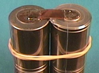
Flux and tin both ends and both sides of the battery bar.
Be generous with the solder this time.
When cool, clean off the flux.
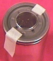
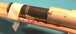
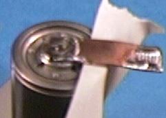
Hold the stick vertically with the button end up.
I use a Panavise with NON-CONDUCTIVE jaws.
Use a piece of tape as shown to avoid shorting the cell.
Put a generous amount of solder on one tip of the hammerhead.
Hold the bar so that the other end rests on the button.
Pre-shaped bars should curve from the button in the direction of the cell.
Apply the iron for no more than 3 seconds!
Don't move the bar until the joint cools.
Solder should have flowed around and made a decent shiny fillet.
Remove the tape and slip a donut on the end under the bar.
Shrink tubing is next.
On the stick that does not have a bar, place a donut over the button end.
I've been using Scotch Double Stick Tape for this.
It's kind of a pain, but I'm considering doing it instead of the masking tape next time.
You don't absolutely need this, but it's not a bad idea.
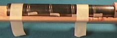
Cut two pieces of 1-1/2" shrink tubing about 3/8" longer than the sticks.
Make sure you cut the ends square.
Slip the tubing over the sticks so that you have equal overhang.
Just jam the shrink into the bar.
Carefully shrink the tubing tight.
Keep the heat moving and quit when it first looks tight.
Now you can neatly label each stick.
The outer wrap will protect it from wear.
 Now that the sticks are insulated, they can be safely joined together.
I clamp the stick that does not have the bar vertically (button end down) with the other stick rubber-banded to it (bar end up with bar centered on other stick).
Sounds complicated but it's not.
Hold the hammerhead tip on the bar while applying rosin core solder on the joint.
Don't forget the 3 seconds rule.
You should end up with a nice shiny fillet around the bar.
When cool, flip the assembly over.
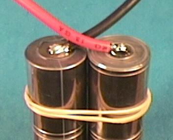
I use 3" wires for all my packs.
This is fairly short but functional, and all packs are consistent.
Long lead requirements should be accommodated on the particular ESC.
Strip 1/4" from a black and a red wire and thoroughly tin them with rosin core solder.
Solder each wire so that it crosses the top of the other stick.
Same rules as for the bar.
Remember, red - button, black - flat.
When cool, you're ready for final packaging.
Now that the sticks are insulated, they can be safely joined together.
I clamp the stick that does not have the bar vertically (button end down) with the other stick rubber-banded to it (bar end up with bar centered on other stick).
Sounds complicated but it's not.
Hold the hammerhead tip on the bar while applying rosin core solder on the joint.
Don't forget the 3 seconds rule.
You should end up with a nice shiny fillet around the bar.
When cool, flip the assembly over.
I use 3" wires for all my packs.
This is fairly short but functional, and all packs are consistent.
Long lead requirements should be accommodated on the particular ESC.
Strip 1/4" from a black and a red wire and thoroughly tin them with rosin core solder.
Solder each wire so that it crosses the top of the other stick.
Same rules as for the bar.
Remember, red - button, black - flat.
When cool, you're ready for final packaging.
Slip the wires through one of the battery caps and put the caps on the assembled sticks.
Cut a piece of 2-1/2" shrink tubing about 3/8" longer than the sticks.
Make sure you cut the ends square.
Slip the tubing over the sticks so that you have equal overhang.
Carefully shrink the tubing tight.
That does it!
Add connectors and Velcro and you're done.