
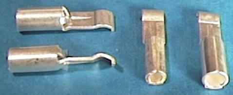
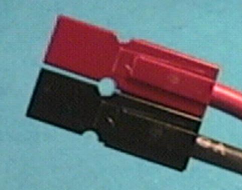
The first picture shows APP contacts. Feature #1 - there is only one type of contact (no male/female pairs)! The contacts are made of steel and plated with silver. The Tamiya-style connectors (tinned steel male and female in white nylon housing) that are ubiquitous in the model car hobby soon lose there spring tension. When this happens, resistance goes up dramatically, and these connectors sometimes melt. Do not ever use these! The APP design provides tremendous contact pressure that remains high with repeated insertions. Gold plating has the advantage that it does not corrode, but these contacts are self-cleaning, and silver is a better conductor of electricity. Note that the two contacts on the right have different openings. The larger accommodates up to 13-gauge wire, while the smaller will handle up to 16-gauge. Other than wire size, the contacts are the same, and use the same housings. The lip on the end of the contact catches on the edge of a piece of metal in the housing. This prevents the contact from backing out. It is important to be sure that this happens when assembling connectors. You will hear a loud click when the contact snaps into place.
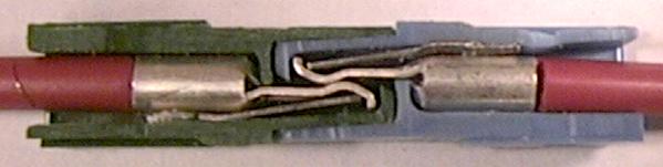
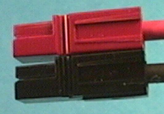
The next shot is a cutaway view of mated connectors. Below the contact is a piece of spring steel that is part of the shell. It provides consistent, reliable pressure to the connection. You can also see the complete symmetry of the two connectors. If you look carefully, you can see the raised portion and the recessed portion.
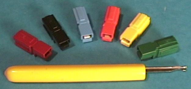
This photo shows housings and a tool designed to aid in installing and removing contacts. You can remove contacts with an X-acto blade and/or a jeweler's screwdriver, but the tool is less frustrating. The tool also can help with inserting the contacts. The tool costs less than ten bucks, or about what you will save on two or three pairs of APP compared to the Astro or Goldstecker connectors. The housings are available in several colors. I generally buy packs of 20 with 10 red and 10 black.
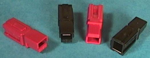
The next photo shows different shell views. The one on the right has the wire end facing, and the others the mating end. There is only one shape of shell. No polarity is inherent in the shell or contact. Each shell has two raised shapes and two recessed shapes that allow the connectors to interlock. This is what provides the versatility. Polarity is determined by how you plug them together. You cannot depend on color alone for polarity control. I frequently have trouble plugging my packs in because I have black to red and do not notice it!
There are two basic choices: side-by-side, and top-to-bottom. With side to side you can choose which color goes on which side. With top-to-bottom you do not have a choice. If red is on top of black, the mating connector must be black on top of red. Think about it. I have standardized on side-by-side for battery packs and ESC inputs. My choice is "red - rear", meaning the red connector is inserted into the black connector from the rear (wire end). Some people stick a toothpick in the hole seen in the side-by-side configuration to keep them together. I have not found it to be a problem. Production tolerances yield a few that are quite loose and a few quite tight. I save the loose ones for chargers where I might want to reconfigure to charge something other than my "standard" configuration.
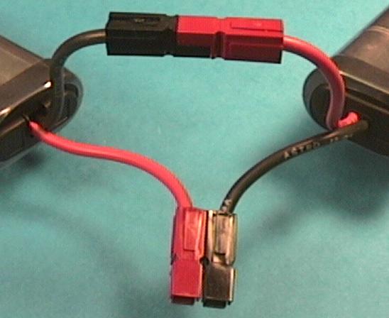
Continuing with the versatility theme, the next picture shows two packs connected in series. Any number of packs can be connected this way, and quickly returned to standard configuration. Any number of wires can be made into an M x N group (M rows of N columns). Three side-by-side are used to connect the ESC to the brushless motor on MaxCim systems. I hope you see now the advantages over fixed polarized connector pairs and individual connector pins. There are also disadvantages. They are too big for the smallest applications. For super high performance applications such as F5B they cannot compete with the Goldstecker which can be soldered directly to the cells. As far as resistance, the APP are comparable to the Astro and the Goldstecker (0.6-0.8 milliohms).
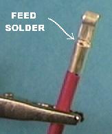
Now let's put some together. It's best to use 13-gauge zillion-strand wire. Some people use these contacts with 12-gauge wire, but it's a pain. In order to get the best connection, the wire should be tinned after stripping 3/16" off the end. Use rosin core solder. It takes a lot of solder to do this, but it's better done before the wire is in the contact. If you globbed the solder, you must remove the excess with solder braid. If you were perfect, the wire will slip right in the contact. For the rest of us, use pliers to shape the end as round as possible. You might have to heat the contact to coax it on the wire. I get the contact started, then heat the contact with a spot of solder on the iron to aid heat transfer. Use pliers to slip the contact down. It should butt up against the insulation. To solder, place a drop of solder on the tip to aid heat transfer. Hold the tip behind the place shown for feeding solder. Slowly feed solder into the opening and gradually move the tip down towards the insulation. Stop feeding solder when you can see it in the hole. Allow to cool and scrape any flux off with an X-acto knife, or use alcohol. If you left any blobbed solder on the contact, shave it off with the knife. Get the appropriate color connector shell. This seems obvious, but sometimes gets overlooked. Look in the shell. You should see a slot in the middle. This is where the blade of the contact must pass through. You should also see a metal plate. The lip of the contact should slide along this plate then snap over the edge. Insert the contact slowly. You should see it coming through the slot. If you have trouble pushing it through, use the tool or a small screwdriver blade. Listen for the snap. You should not be able to pull the wire back out of the shell. After you've seen an installed contact, you should be able to tell an improperly installed one just by looking at the position of the lip.